Input and Output of Lego
NXT Servo Motor  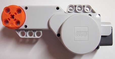 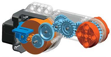 Wiring (RJ12-Connector)
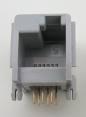
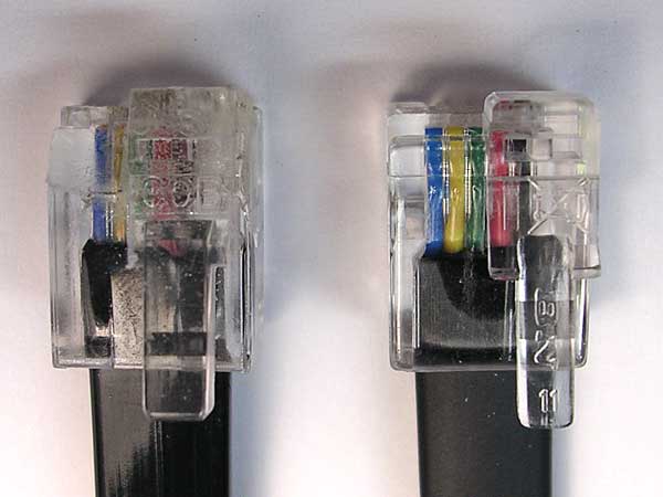
Pins numbering from left
to right: 6 - 5 - 4 - 3 - 2 - 1
Pin number of original
nxt-cable |
cable color |
function |
signal / polarity |
signal form |
| 1 |
white |
motor power supply |
DC 9V + or - |
DC |
| 2 |
black |
motor power supply |
DC 9V - or + |
DC |
| 3 |
red |
rotation detector supply |
ground (0V) |
DC |
| 4 |
green |
rotation detector supply |
+ 4.3 (to 5.0 V) |
DC |
| 5 |
yellow |
rotation detector output 1 |
0 / 4.3 V against 3,
-4.3V / 0V against 4 |
rectangle |
| 6 |
blue |
rotation detector output 2 |
0 / 4.3 V against 3,
-4.3V / 0V against 4 |
rectangle |
The 4 connectors for ratation detection
(pins 3-6) are independent from the 2 motor coil connectors (pins 1-2).
Inputs:
Pins 1 and 2: DC supply/power for motor,
polarity determines rotation direction.
Pins 3 and 4: DC 4.3 V to 5V supply for
rotation detector
Outputs:
Pins 5 and 6: +/- 4.3V DC
rectangle signal against pin 3 or 4
Signal diagrams:
definition of forward rotation:
Each output (pin 5 and pin 6) provides
180 pulses per round of the orange output wheel.
The duty cycle is intended to be 50%:50%
and the phase between 5 and 6 is intended to be 180 degrees.
Like this the motor should have a resolution
of 1 degree (2x180 pulses).
But neither is exactly reproducible; the
duty cycle is more like 45%:55% and therefor also the phase can not be
180 deg but is little less.
However, the two output signals are able
to give the speed and relative angle with an accuracy of 2 degrees
or better, and the rotation direction. But an absolute angle of
the motor can not be detected .
|